Robo-Fish Research: Dual-Piston Ballast
The purpose of this project was to research, choose, and produce a ballast system to control the buoyancy of a robotic fish. Due to its simplicity and reliability, a piston-based ballast system was chosen.
This project presented several challenges, namely:
Required understanding of motor hardware, motor driving software, physical design, and electrical design
System was required to be watertight and fit within a 3” diameter 12” long tube
Inclusion of sensors to know when piston tank was full/empty
Piston Tank Assembly
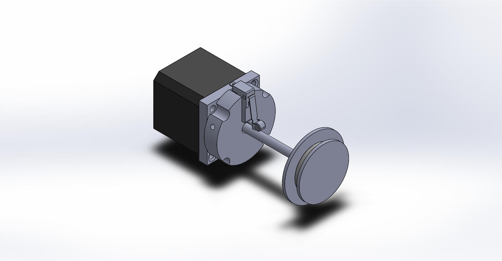
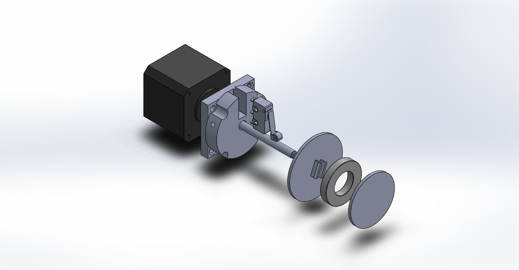
Each piston was constructed from a translational threaded rod stepper motor (black cube above), a large diameter syringe, and several 3d printed parts.
The two main components that were designed were the motor-to-syringe adapter (grey piece closest to the motor) and the two-piece piston head. Each component was designed with a sensor in mind - the adapter included a cutout for a pressure microswitch to detect when the piston head at the bottom of its range of motion, and the piston-head componentry was fabricated to snap-fit around a magnet (pictured above right) that would trigger a hall-effect magnetic switch when the piston-head was fully extended to the end of the syringe.
Big Piston, Small Tube.
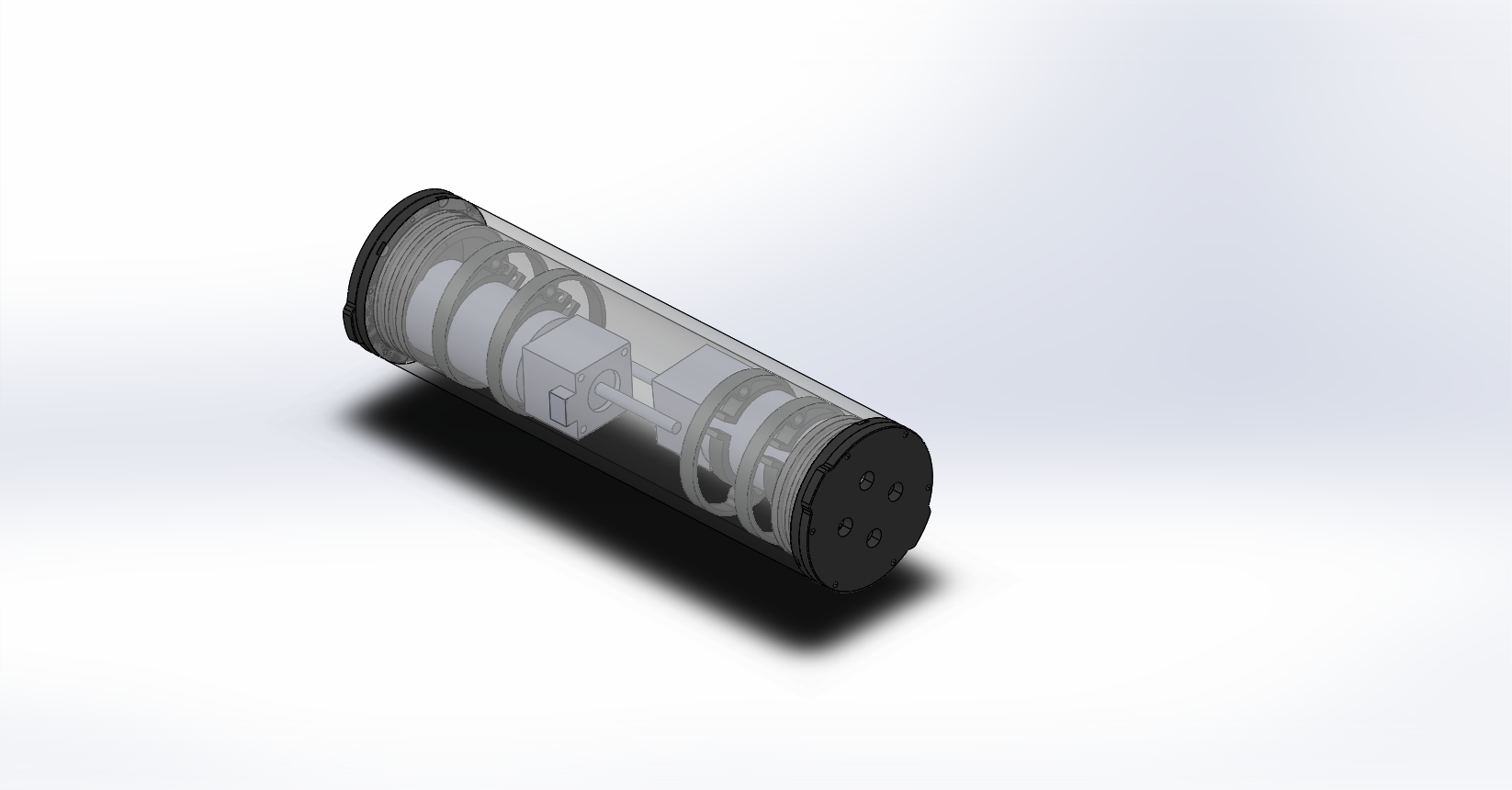
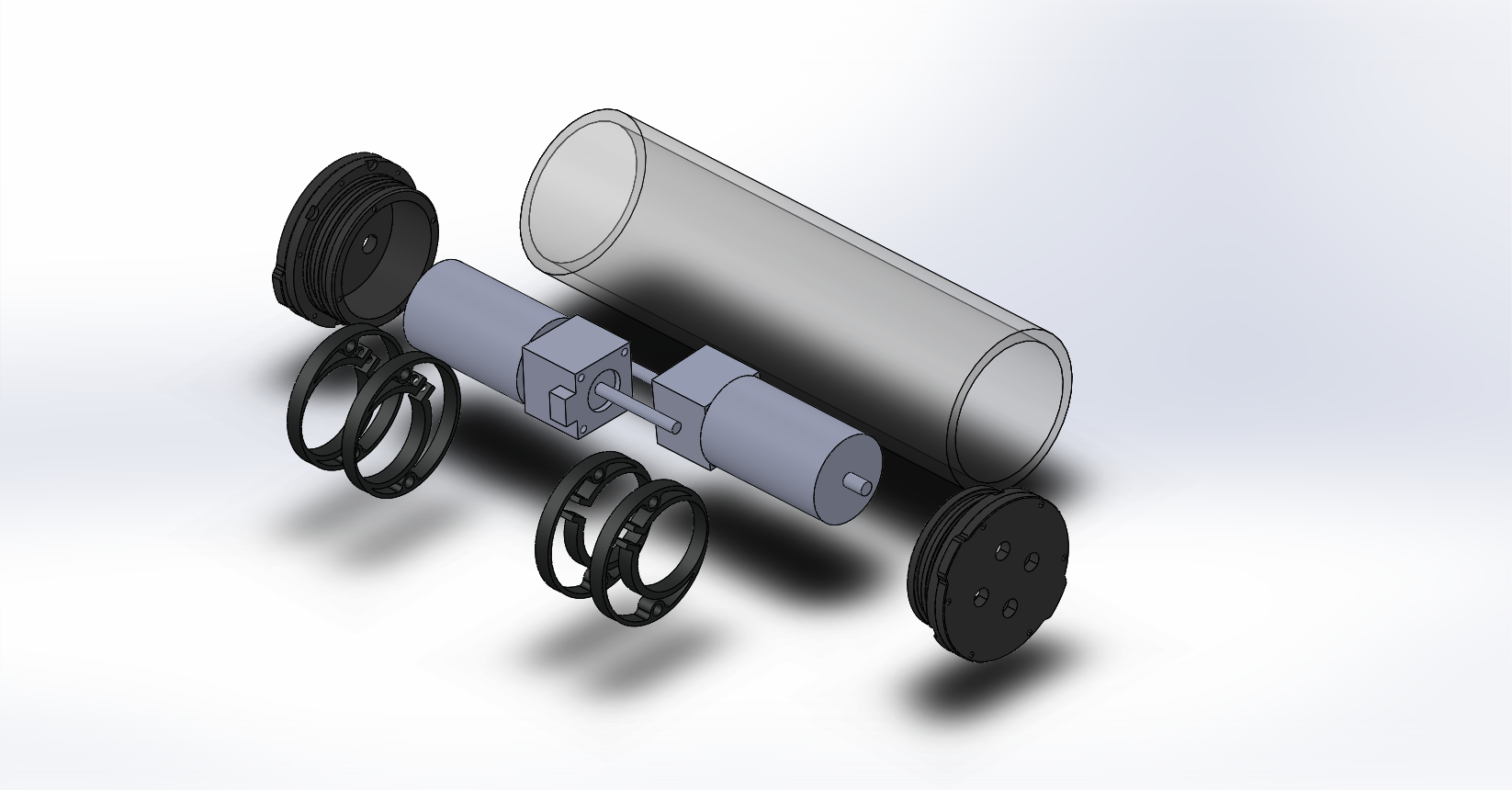
To ensure that the center of buoyancy would stay stationary during filling, two tanks had to be placed end-to-end within the watertight ballast hull. Because of the large size of each piston-tank and the range-of-motion constraints of the threaded rod stepper motor, custom mounting brackets were designed to hold the piston tanks in positions that would not conflict with other elements of the ballast system.
Assembly and Wiring
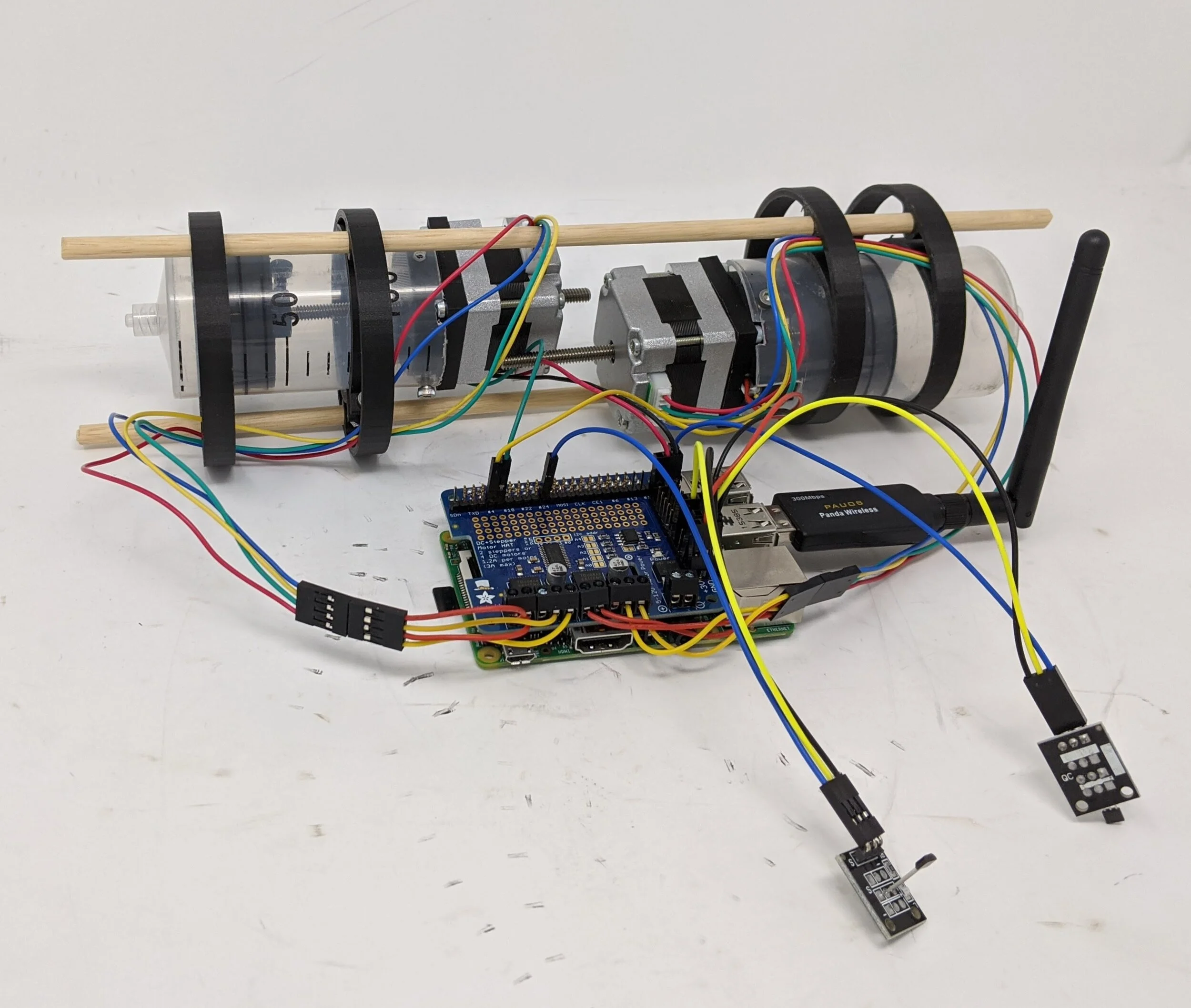
The pistons tanks were both controlled through a stepper motor Raspberry Pi-Hat, and the pressure and magnetic sensors were connected to the general-purpose-input-output pins of the Raspberry Pi. To control the stepper motor position, programs for draining and filling the piston tanks were written in Python and run natively on the Raspberry Pi over wifi.
What did I learn?
This project was difficult to bring to fruition because of the variety of different skill areas that had to be brought together to create a functioning final product. For perspective, at the beginning of this project I had a novice understanding of motor control software and low-level CAD/3D Design experience. Completing the multiple rounds of testing and iteration required major growth in both of these areas, and required basic proficiency in working with wiring, soldering, and electronics (which was completely new) .
All in all, the open-ended nature of this research experience taught me a lot about the process of prototyping, but also about the process of managing one-man-team projects where I must keep myself accountable to my goals and schedule.